Turning an RC Transmitter Into A Flight Sim Controller
yep
below you'll find how I used a transmitter as a joystick.. this link lets you use the computer as the joystick to control the servos:\ http://www.mh.ttu.ee/risto/rc/electronics/pc2rcv2.htm
I built and adapter to plug my airtronics vgr4 into my mic input so I could use it to control the airplane in FMS (r/c airplane flight simulator)
here are my notes:
some adapters
futaba to usb:\ http://www.milehighwings.com/usb\_cables.htm (autolearn, \$39)\ http://www.geocities.com/simblaster/sbinstructions.html (cheesy, \$39)\ or... airtronics vanguard fm vg4r\ http://www.rc-circuits.com/ (buy it from these guys)\ http://www.heliguy.com/nexus/fmsinterface.html (pictures of the hookup)\
alternative
build your own adapter to go from the 5 pin out on the back of the transmitter to a 1/8th" phono plug you can plug into your mic input. Use SmartPropoPlus to interface to FMS. It actually works. But, if you blow something up (i broke a few things) it is not my fault.. if you try any of this and something breaks, you are on your own.
tips in an email i sent to someon
That's cool an old IBM keyboard plug will work. I dug for a while and found one in my pile of junk. Wiring it up is easy. you need a mono 1/8th" plug. when you look at the back of the transmitter, you'll notice the pins are rotated 1/4 turn clockwise. One wire hooks to the middle (found at the 3 o'clock position) pin. The other wire hooks to the bottom pin (near the 5 o'clock)
Sadly, i do not know which wire goes to the tip of the mono plug and which goes to the sleeve (my ohms meter bit the dust last night so i cannot check). But, i do know you can reverse them without blowing anything up... it's just that the program can't read the joysticks when it is backwards..
Download and install the flightsimulator from:
http://n.ethz.ch/student/mmoeller/fms/index\_e.html
I downloaded Version 2.0 Alpha 8.5 but i just noticed beta 7.0 is the recommended version. you decide.
Find two apps. winmmppm.dll.zip can be found when searching for SmartPropoPlus. I don't know where i found analyser31.exe... it was written by philippe g. de coninck in 2004. It may be called Simple PCM signal analyser v 3.1.
unzip winmmPPM.dll.zip and drop the dll into the FMS directory. ( C:\Program Files\FMS) This tells FMS how to use your transmitter as a controller.
you'll use analyser31.exe to test your controller/mic input:
Plug the adapter into your mic input. Turn the transmitter on. Fiddle with the volume controls until there is a loud, annoying noise coming out of your speakers (you may want to mute the output)
Now start analyser31.exe.
click on the interface menu and select "Audio (MIC)"
now, click the "MONITOR" button near the bottom center. You'll see some bars.. the bars should move around when you move the sticks. If not, there's a problem (check your recording volumes, wired up backwards, etc.) The bars are jittery and don't always center out. I think this is normal.
Once you get something that looks about right, stop the MONITOR and close the app. It is a crappy app.. you may have to reboot before it will let go of the mic input and allow FMS to work.
Start FMS\ click controls\ click analog control.\ highlight joysitck interface, click Resources.\
it should say "smartPropoPlus - general PPM" with 6 axes for Joystick 1. If not, you somehow did not install the winmm dll file correctly.
if all is well, click OK
click mapping/calibration. Move the sticks around, they should move those bar graphs around. Click calibrate and follow the instructions. the bars should be moving along with your joysticks.
The Mapping section will define which channel is assigned to which control and define if it is inverted or not. I do not know what Exp means.
My mapping is:\ rudder - 1\ elevator - 3 - inverted\ aileron - 2 - inverted\ throttle - 4 - inverted.\
Your inverted settings may be different than mine.
Click OK.
Press "i" to reset the flight sim. Give the plane some gas and take off.
Interfacing an AVR with an ISA Nic
My first microcontroller project
(This was written in early 2002)
I'd been wanting to play with some embedded systems for quite some time but didn't really know where to start and didn't have any impressive ideas. I mean, really, how many computer controlled thermostats or robots does this world need.
One day I ran across the worlds smallest web server. I thought this was pretty cool and wondered just how hard it would be to internet-enable something with an embedded web server. I went out and bought a TINI to play with some ideas, but it was back ordered... for 3 months. While I was waiting i found the \$25 web server and thought, what the hell, I can do that.
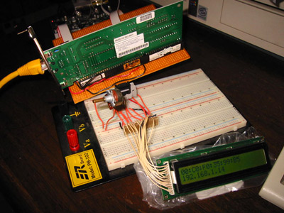
I went out and bought me an STK-500 developer board and an Atmel AT90S8515 8-bit microcontroller chip. Good times... I needed to do something easy with it to get started, so I bought an LCD from a surplus electronics place. It was easy enough to wire up the LCD and write some assembly and C programs to display clever messages to impress my friends.
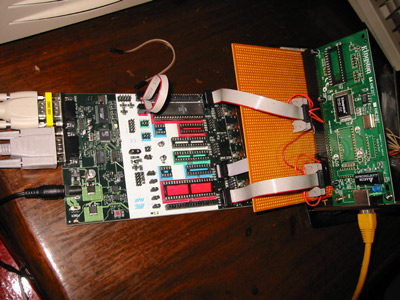
Anyway, I decided it was time to wire up an old 3com ISA ethernet card I got for free from work and try to "internet-enable" something. I couldn't think of anything cool to hook up so I as stuck.
Then I ran across this. HOT DAMN!!! hooking a nic to an avr and an lcd to display udp messages sent to the nic's IP.. how perfect is that? Thanks Dave, whomever you are.
So, I used that PDF (careful, there are mistakes in there) and info
from
the $25 web server page to wire everything up. It didn't work. Imagine
that. Well, whoever didn't put in big bold letters: 'Hey dumbass, you
need an ne2000 card.' needs to get shot. My 3com card is not ne2000,
whatever the hell that means. So, i got one off ebay for \$1.99, plugged
it in, turned it on and BOOM! the freakin' thing works.
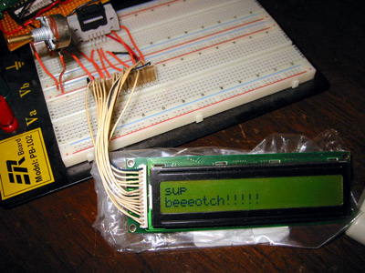
Here's what it does. You compile the IP address in the code and download it to the avr. When you turn it on, the chip initializes the nic and the lcd. It probes the card for a mac address and displays that plus the IP on the LCD. It then sits and listens on port 987 for a UDP packet. When it gets a packet, it decodes it and sends the data to the LCD. I wrote a little java app that will take in a string and send it to an IP using UDP. When you hit send, the message appears on the LCD. How cool is that?
Here's some of Dave's code: ; we have now advanced the read pointer up to the first byte of ; the "data" portion of the IP packet ; ok, now look back at the protocol field and jump to the right ; code to handle the packet type ldi r18,1 ;icmp cp r19, r18 breq ne2k_read_packet_icmp ldi r18,6 ;tcp cp r19, r18 breq ne2k_read_packet_tcp ldi r18, 17 ; udp cp r19, r18 breq ne2k_read_packet_udp
right... needless to say I didn't write any of the code behind this project. I did have to modify it to get it to work, though...
The nic cost \$2, \$8 for the microcontroller, and \$10 for the LCD. Everything else I bought I didn't really need (like the STK-500, breadboard, perfboard, dirty hookers, etc.) but it sure as hell made life much easier.
That's great. Now what?
Now that I've figured out how to work with microcontrollers, and getting some random device to respond to commands sent through the internet I'm well on my way to finally getting my toaster to burn my english muffins from the other side of the planet.